Location
| When gating a part, consider wall thickness variations. Most often, gating in the thickest region of the part is optimal to prevent sinks and other molding related defects. Consider venting last place to fill and other regions that could trap gas. |
Tolerancing
| When gating a part, consider wall thickness variations. Most often, gating in the thickest region of the part is optimal to prevent sinks and other molding related defects. Consider venting last place to fill and other regions that could trap gas. |
Weld Lines
| When gating a part, consider wall thickness variations. Most often, gating in the thickest region of the part is optimal to prevent sinks and other molding related defects. Consider venting last place to fill and other regions that could trap gas. |
Type
| When gating a part, consider wall thickness variations. Most often, gating in the thickest region of the part is optimal to prevent sinks and other molding related defects. Consider venting last place to fill and other regions that could trap gas. |
Tunnel Gate
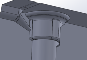
Advantage Disadvantage |
Tab Gate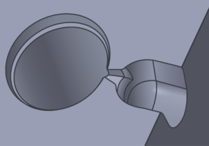
Advantage Disadvantage |
Valve Gate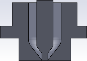
Advantage Disadvantage |
Geometry
| Runner systems should be geometrically balanced to ensure even filling . This means identical flow lengths to each cavity with adequate venting designed throughout. |
Tolerancing
| The steel accuracy from one runner branch to another is extremely important and often overlooked. Variations in steel can lead to unbalanced filling conditions within the mold. |
Size
| Runner sizing depends largely on the material type and length of flow. A flow simulation is often a helpful tool to accurately determine the proper runner size for a given material and mold cavitation. |
Type
| There are many types of runner system designs, each one with its own unique purpose. The table below illustrates a few common designs and their intended purpose. |
Full Round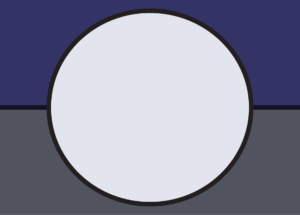
Advantage Disadvantage |
Trapezoid 
Advantage Disadvantage |
Hot Manifold
Advantage Disadvantage |
Location
| When ejecting a part, it is important to select an area that will allow for adequate ejection while reducing the potential for part deformation or potential tooling damage. |
Tolerancing
| The fit between holes and pin/blade sizes should be within +/- 0.0003 inches to allow for a smooth fit but also reducing the risk for flash in this area. |
Size
| Over time, the ejection system within a mold will wear. It is recommended to utilize standard size components, whenever possible. |
Type
| There are many types of ejection designs, each one with its own unique purpose. The table below illustrates a few common designs and their intended purpose. |
Ejector Pins Blades Sleeves
Advantage Disadvantage |
Stripper Plate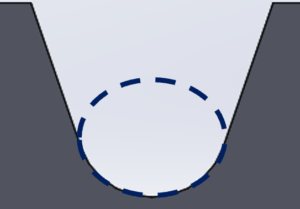
Advantage Disadvantage |
Lifters
Advantage Disadvantage |
Location
| Mold plates should be designed for maximum cooling or heating. Water line fittings should be placed on the non-operator side of the press and recessed into the mold plates, whenever possible. |
Uniform Cooling
| Uniform cooling is essential to minimize part defects that are directly related to cooling. A flow simulation is a helpful tool to accurately determine proper mold cooling. |
Size
| Cooling lines should be designed to achieve an adequate flow rate. Calculating a Reynolds number greater than 10,000 is a useful method to determine adequate flow rate through the water line(s). |
Type
| Cooling lines should be designed to achieve an adequate flow rate. Calculating a Reynolds number greater than 10,000 is a useful method to determine adequate flow rate through the water line(s). |
Series Circuits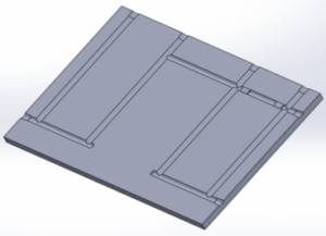
Advantage Disadvantage |
Parallel Circuits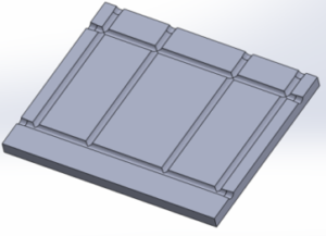
Advantage Disadvantage |
Baffles & Bubblers
Advantage Disadvantage |

