Scientific Molding
Process validation is the final step in the development cycle before the tool & product can be deemed fit for production. During this process, scientific molding principles should be applied to establish the nominal running conditions for that given mold, material, etc. Scientific molding consists of sequential steps that are followed to establish nominal fill time and pressure, gate freeze time, pack pressure, cavity pressure, cycle time, and clamp tonnage. From there, key process parameters are often tested through the means of a Design of Experiment (DOE) to reach the process window that will be duplicated each production run. The last step in the validation is to simulate an extended production run, often referred to the PQ stage of the process. Once the tool is fully qualified, a master file is created which can be loaded at each molding machine to replicate during the subsequent production runs.
To review a full protocol of our IQ/OQ/PQ procedure, we encourage you to reach out and discuss further.
Here are a few essentials to keep in mind when developing a tool for production as well as a deeper dive into our validation process.
General Considerations
- 1.) Will tool fit into intended press?
- 2.) Is the shot size large enough to fill part?
- 3.) Does shot size utilize enough material to reduce degradation concerns?
- 4.) Does the press have enough daylight/opening to properly eject part?
- 5.) Is the press fitted with pressure sensor capability?
- 6.) Has a two-stage decoupled process been determined?
- 7.) Is the raw material properly dried?
- 8.) Is the cooling/heating of the tool properly installed?
- 9.) Has the clamp tonnage been determined and set?
- 10.) Does the actual cycle time meet the quoted time?
- 11.) Are ejector knockouts tied into the tool?
Auxiliary Equipment
- 1.) Is EOAT required for ejection/pick and placement of parts?
- 2.) Is cavity separation required?
- 3.) Has packaging method been identified (bulk, layer, etc.)?
- 4.) Are there any mold protect cameras / visions systems required?
- 5.) Are there any conveyors and/or additional part handling required, post ejection?

Scientific Molding: Process Development
Mold Validation: Each mold is thoroughly evaluated by a Master Molder (Level I – Level III) Process Engineer

Step 1: Installation Qualification (IQ)
An Installation qualification is essentially a documented Bill of Materials of all the intended equipment that will be needed to mold a product (i.e.: Machine type / tonnage, Robotics, dryer(s), chillers, eDART equipment, etc.).

Step 2: Operational Qualification (OQ)
This is where much of the mold validation work / time is spent. Our process engineering team will develop a scientific molding process to target several key process variables. From there, a DOE is performed to test high / low limits of the process. During this time, extensive metrology work is performed on all key print variables. Measurement technique / correlation with our client is crucial during this stage.

Step 3: Performance Qualification (PQ)
A PQ is the final phase in the process development cycle. This is where an extended 8-24 hour production simulation run will occur on the mold to ensure we can move into full scale production. A metrology report on the critical dimensions is also performed as the last piece of confirmation with our clients.
Scientific Molding: Process Development
Shown below are several process development studies that are performed during the OQ portion of the mold validation
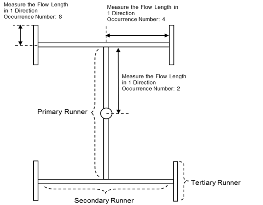
Clamp Tonnage Optimization
Calculating adequate clamp tonnage is an important step in the mold validation as over clamping can lead to premature wear on the tool and potentially damage to fragile steel. Clamp tonnage is calculated using a variety of methods either using Moldflow or machine values. To calculate, you take the projected area of the finished part & runner * the number of cavities * the end of cavity pressure(tons). Example 2.7” projected area * 8 cavities * 7,000 psi or 3.5 tons/in2 = 75.6 tons required.
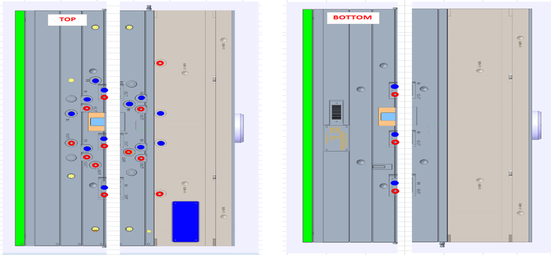
Waterline Schematic / Flow Rate
Water lines are tested during validation to confirm adequate flow rate through each channel. Once confirmed, a process engineer will complete a schematic of the water line connections so that it can be replicated the same way during production start up.
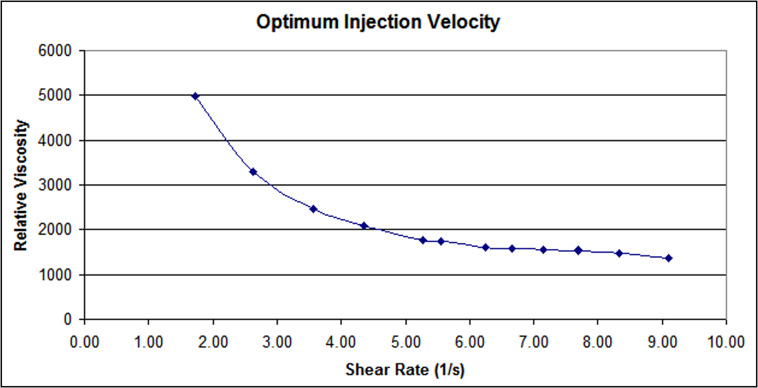
Optimal Injection Velocity
The purpose of this study is to determine the which speed and fill time will produce a consistent viscosity from shot-to-shot. The study is performed by gradually slowing down your injection velocity and calculating the shear rate (X-Axis) as well as calculating the Relative Viscosity (Y-Axis). Shear is calculated by reciprocal seconds (1/fill time). Relative Viscosity is calculated by your injection pressure * fill time. The optimal speed is determined when the graphs begins to flatten, and viscosity is stabilized.
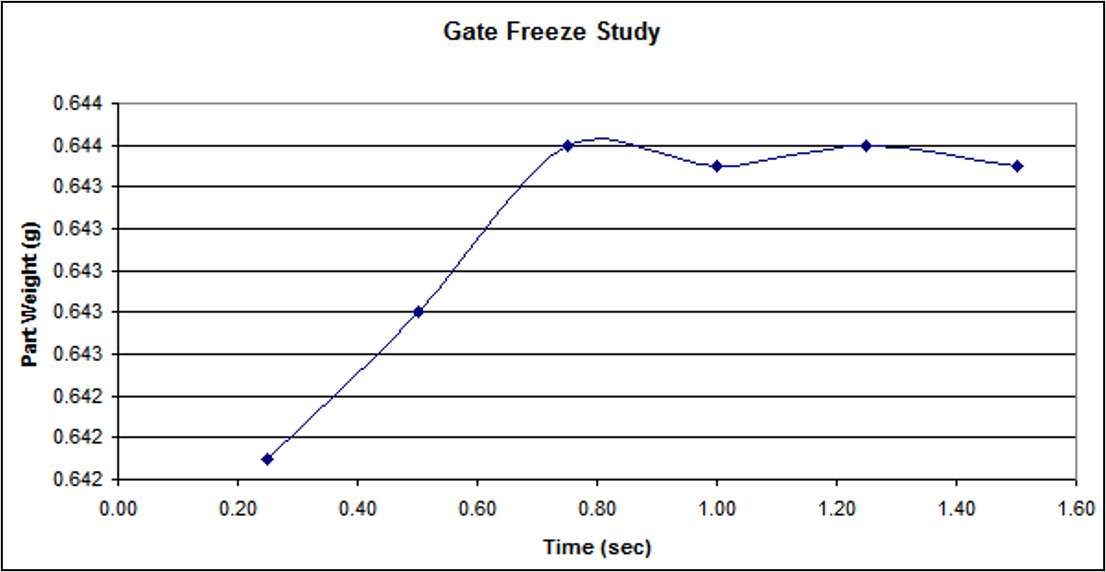
Gate Freeze Study
The purpose of this study is to determine when “enough” material has entered the cavity and when the gate has physically frozen off, prevent further material from entering the cavity. The goal of this study is to adjust your hold time (while keeping your cycle time consistent) and measuring the part weight over time. When the part weight begins to level out, you know your gate is frozen and no additional material can enter the cavity.
Cavity Pressure Optimization
Cavity pressure optimization requires specific hardware and software to accurately measure pressure in the cavity, which is the most accurate form of pressure monitoring available. A sensor is placed strategically at the end of fill in the mold.
When plastic flows over that sensor, a pressure reading is provided. A process engineer can then visually examine the finished product to determine if the part is free of non-fills, sink, flash, etc. From there, limits can be established around the nominal cavity pressure and used for shot-to-shot monitoring in production. Product that does not fall within the acceptable process window can automatically be discarded with the use of an EOAT / Robotics.