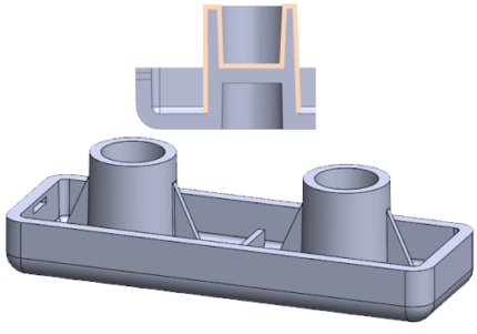
Nominal Wall Thickness
Draft
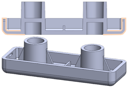
Nominal Wall Thickness
Original Part Design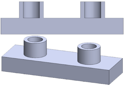
| Different wall thickness between boss and body of part can lead to sinks & voids in that region. |
| Increased cycle time to cool these regions will lead to increased part cost. |
| Potential for dimensional issues related to thick regions. |
Modified Part Design
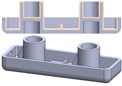
| Removed excess material. |
| Nominal wall thickness will reduce sinks and voids. |
| Reduced shrink variations (improved dimensional stability). |
| Improved part quality (high volume areas are prone to sink marks). |
| Faster cycle time will lead to lower part cost. |
Draft
Original Part Design
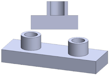
| Lack of draft can lead to increased pressure on ejection system and potential for damage to system. |
| Quality issues possible (drag marks & part deformation). |
| A-half assist could be required depending how the part shrinks to the cavity / core detail. |
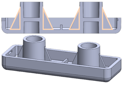
Modified Part Design
| Draft added to part body & bosses to help aid ejection resulting in less stress on ejection system. |
| Faster cycle times can often be achieved since the number of ejector strokes can be reduced. |
| Drag marks are often dramatically reduced or fully eliminated. |
| 1/8° degree minimum (higher when allowed based on part function). |
Radii
Gussets & Ribs
Radii
Original Part Design
| No radii on part. |
| Difficult to produce sharp corners in tooling (exterior molding). |
| Sharp corners can become weak points in part, resulting in stress cracking & part damage. |
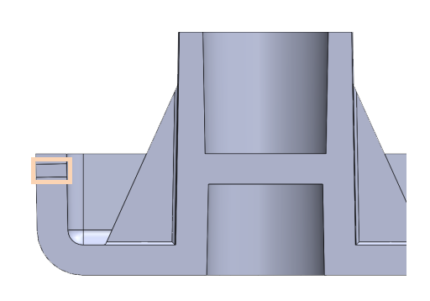
Modified Part Design
| Radii used with void coring to keep consistent wall thickness. |
| Inner radii recommended to be ½ min wall thickness. |
| Outside radii recommended to be inside radii + wall thickness. |
| Can help improve filling conditions as well as part strength. |
Gussets & Ribs
Original Part Design 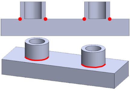
| Potential for part deformation in boss areas due to heat-concentrated regions. Usually, a challenging region to place cooling lines. |
| Poor rigidity & part strength in the area that intersects the main body of the part. Especially, under loading conditions. |
Modified Part Design
| Ribs added to increase part rigidity & dimensional stability. |
| Ribs are typically thinner than primary wall to help reduce issues with sink. |
| Gussets are typically triangular shaped. |
| Both features should be drafted adequately and should not impact overall manufacturability. |
Undercuts
Unscrewing Cores
Undercuts
Original Part Design 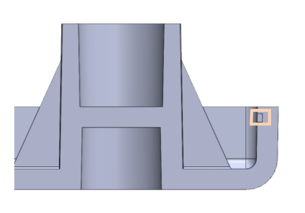
| Undercuts are common on many injection molded parts. |
| Undercut in part above (right wall) could be produced with intricate tooling (i.e. Lifter) depending on distance of pull. |
| Increased tooling cost. |
| Increased chance of quality issues (flash). |
Modified Part Design
| Undercut redesigned to go through entire part wall (left wall), which can be produced using a slide insert. |
| Reduces the complexity of the mold design. |
| Reduces the chance of quality issues that could occur. |
Unscrewing Cores
Modified Part Design: Key Considerations 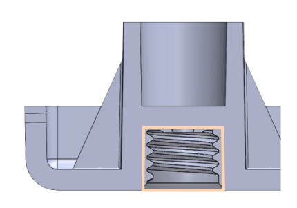
| Part volume can drive they type of unscrewing coring (hand-loads vs. servo motor). |
| Will the threads be reused in applications as this can be a key driver. Plastic threads will wear over repeated use. |
| Thread pitch is another key consideration as some systems cannot tolerate a fine thread pitch. |
Original Part Design
Modified Part Design
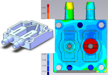
Original Part Design
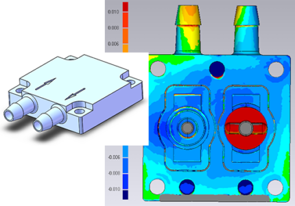
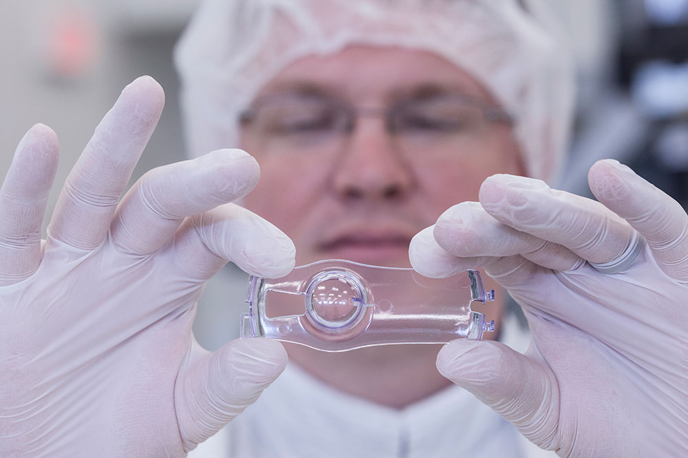
| 2-Cavity cold runner transfer tool that was awarded to Plastikos to run production on a microfluidic device. |
| Nominal wall thickness was 0.320” and our client was experiencing intermittent leak issues in assembly. This was also the region closest to the gate. |
| It was determined the leak was caused by a sink condition that occurred from such a thick wall. That sink mark would cause a depression in plastic ranging from 0.006” – 0.007”, as indicated in the scanning technology, shown above. |
Modified Part Design
| Void coring was added to reduce the nominal wall thickness to approximately 0.080”. |
| Raw material consumption was reduced by ~50% on part and runner, which also reduced the product cycle time. |
| Sink in this region was improved dramatically and the flatness on the part was improved to 0.002” – 0.003”. |
| Customer yields improved along with the ability to reduce parts cost from the cycle time savings and raw material consumption. |

